
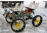
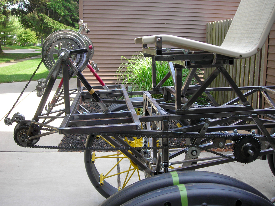
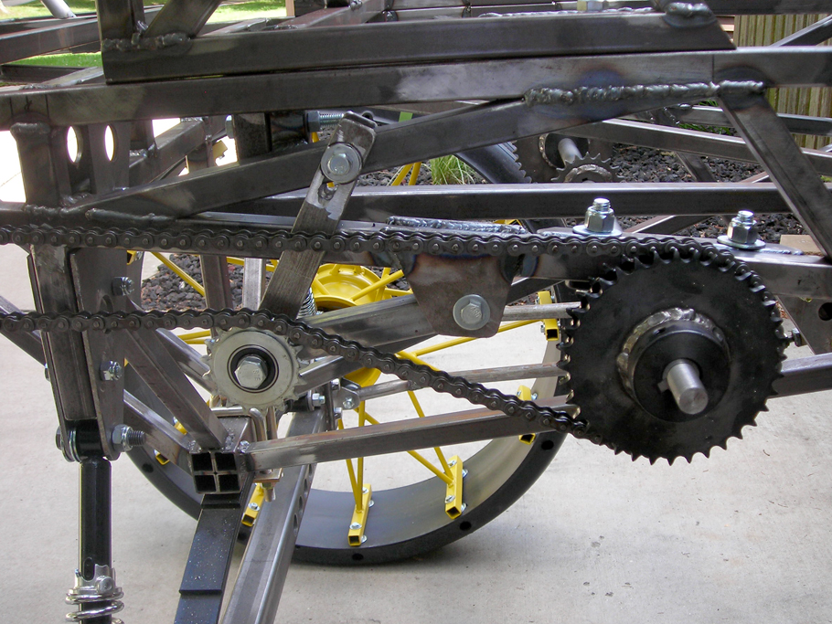
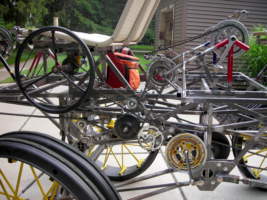
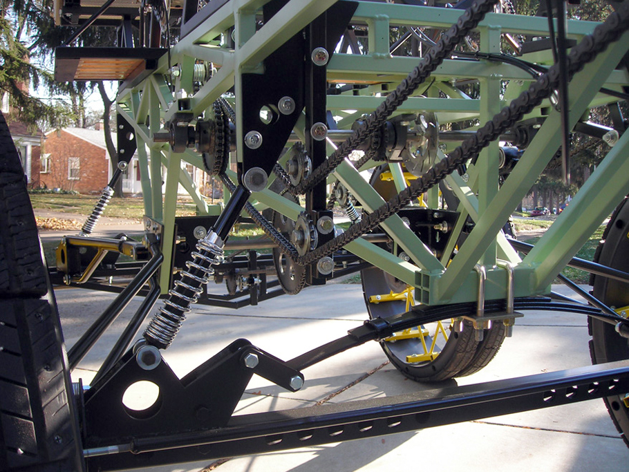
The crank sprocket for each pedal set drives a bicycle free-wheel allowing the pedals to "coast". A #40 sprocket has been added to each free-wheel, #40 chains connect all pedal sets to a single primary 1-inch diameter jack-shaft. The primary jack-shaft then connects to a central jack-shaft.
Questions contact:
tom.wilson@thirstybeachlandscaping.com
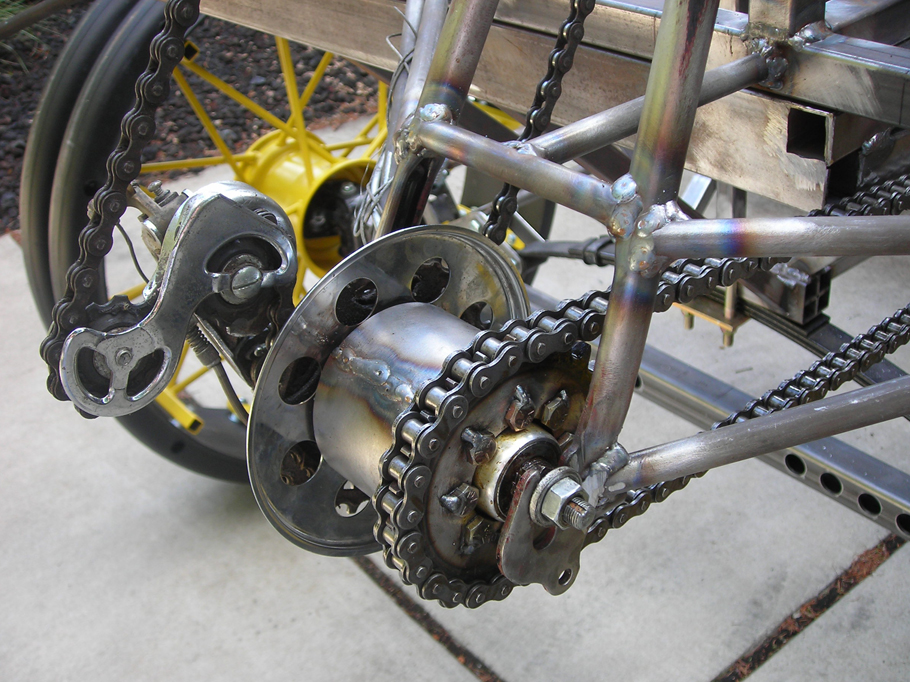
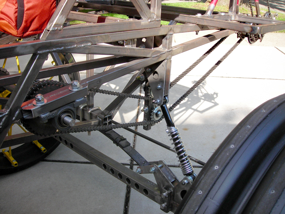
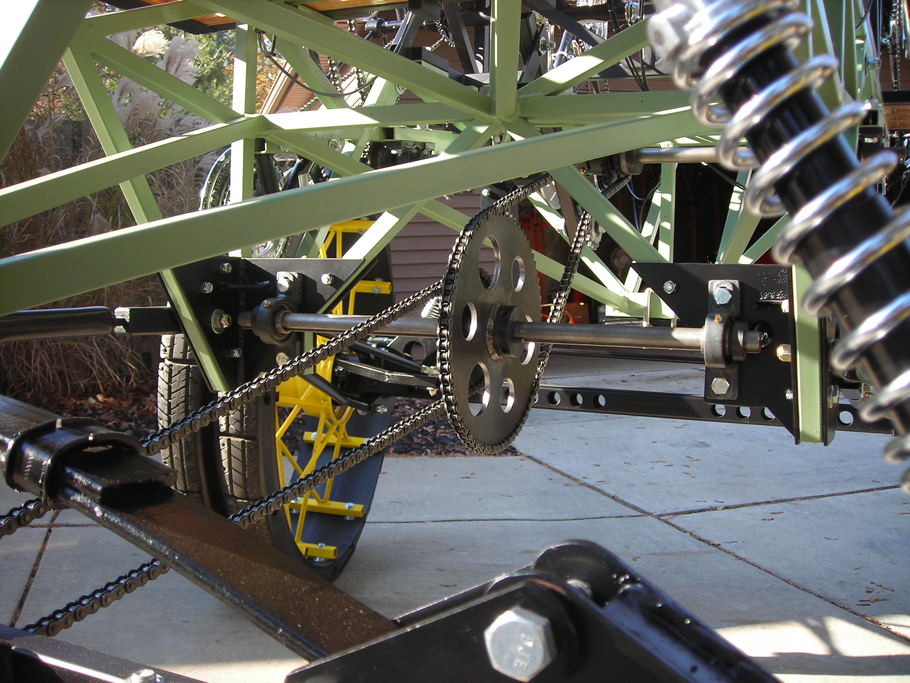
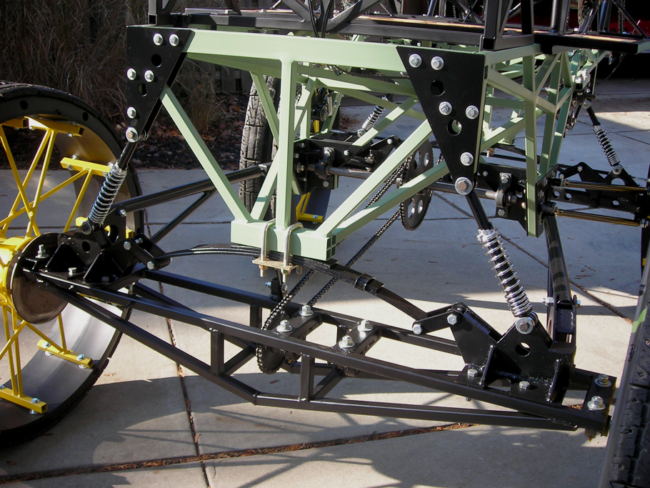
The centerline of the central jack-shaft is aligned with the pivot points of the rear trailing arm and frame connection. This alignment allows the chain tension to remain constant as the rear axle moves up and down. The chain connection between the central jack-shaft and rear axle is located at the center of the axle to minimize chain movement as the rear axle twists. The rear axle is split to allow the wheels to travel at different speeds during turns. Drive is through the left rear wheel while the right wheel spins free.
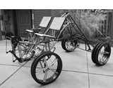
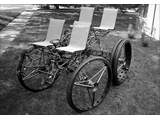
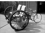
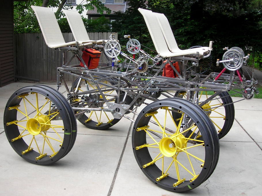
Bare Metal with Drivetrain
July 2008
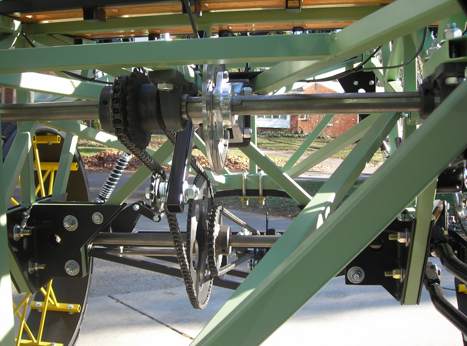
Primary and Central Jack-Shafts
|
|
|
|
|
|
|

|
|
Click to View Larger Image & Details